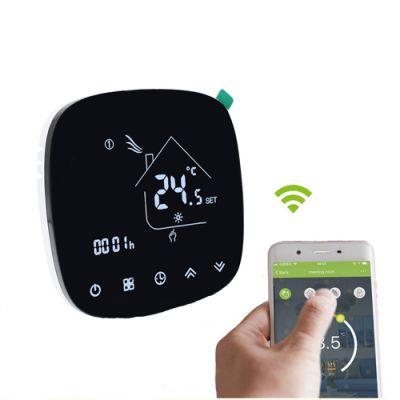


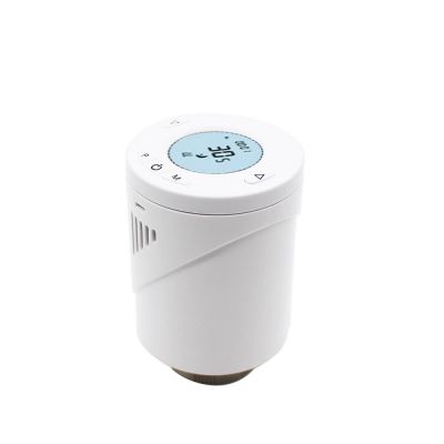


Hotowell Fan Coil Thermostat 240 Vac Wifi Programmable Thermostat with Nest Shape
HTW-WF06-FC series Smart Wifi fan coil thermostat is widely used in these environments like Homes, Residential buildings, Schools, Hotels, Hospitals, Offices and etc. to main an ideal room temperature purpose.
Hotowell Fan Coil Thermostat 240 Vac Wifi Programmable Thermostat with Nest Shape
>> General
HTW-WF06-FC series Smart Wifi fan coil thermostat is widely used in these environments like Homes, Residential buildings, Schools, Hotels, Hospitals, Offices and etc. to main an ideal room temperature purpose.


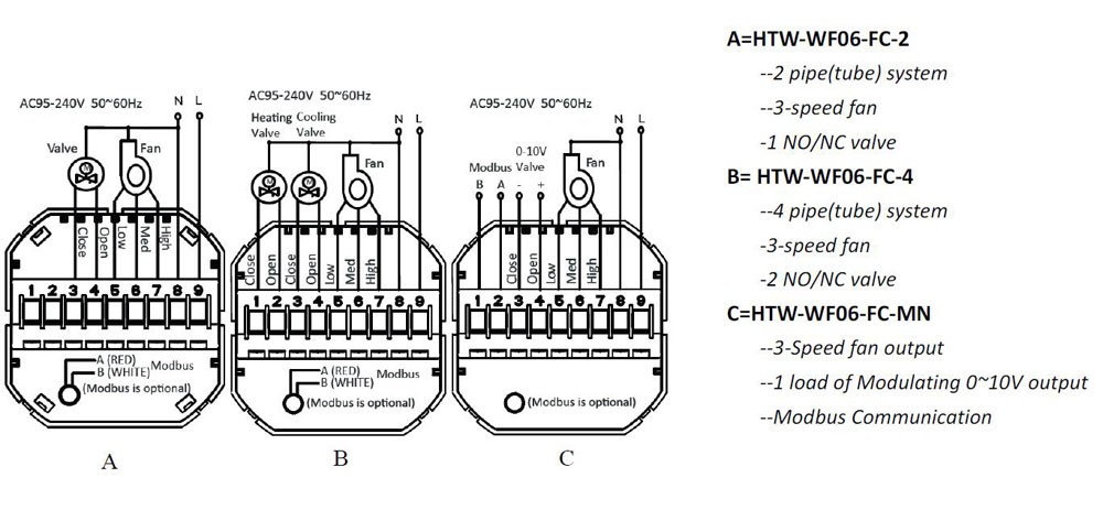
>> Ordering Guide
>> Typical Wiring
>> Specifications
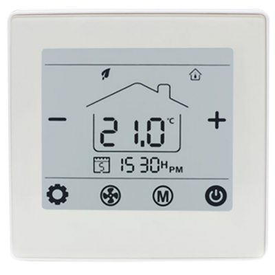
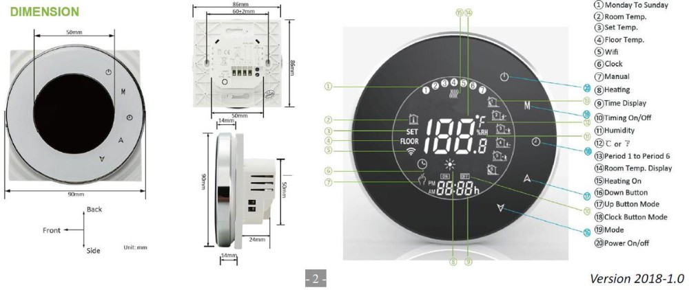
>> Dimensions and Display
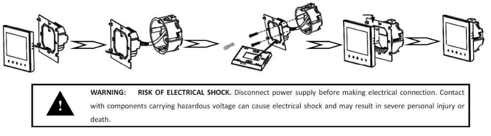
>> Installation
* Make sure the power is OFF! Try turning ON your heating/cooling system by changing the temperature. If you can't get the system to turn ON in 5 minutes, you'll know the power is OFF.
* Take off the installation faceplate by grasping and gently pulling, then connect voltage supply/load output/external sensor(if with) wires respectively to appropriate terminals.
* Fix the installation plate onto the electric junction box with screws packed in the box.
* Fasten the thermostat display part and the installation faceplate through the groove.(Installation process completed)